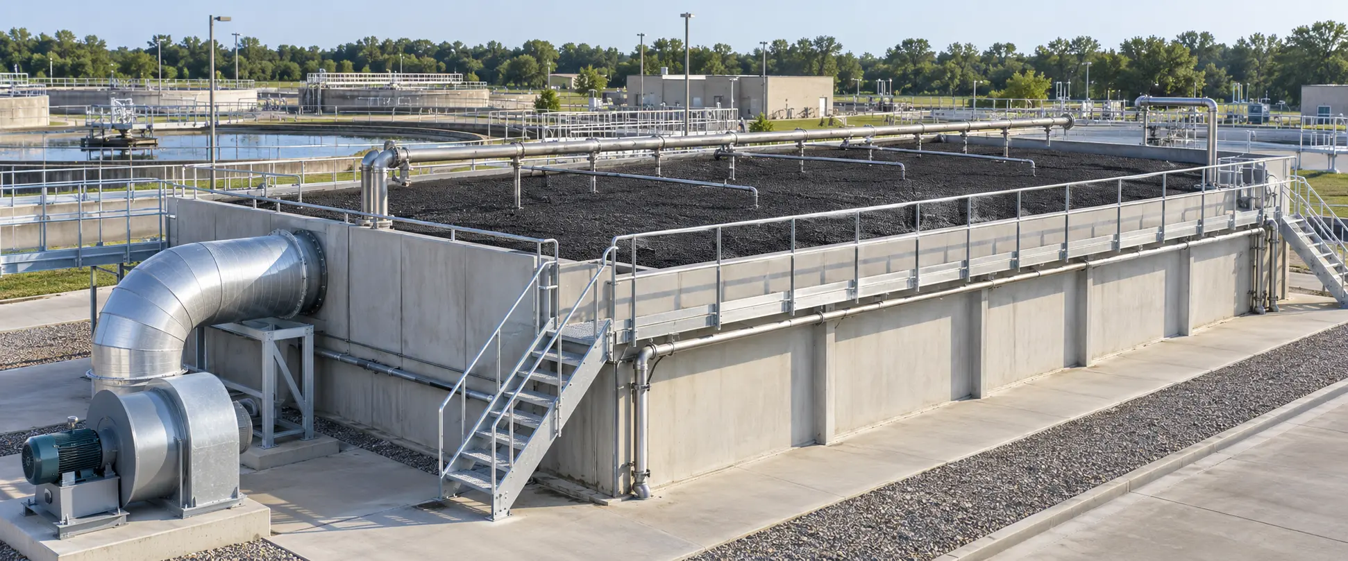
Core design message — GES generally begins preliminary evaluation of many packed-bed municipal and industrial odor and VOC biofilters in the 30- to 60-second EBRT range. Some well-characterized odor systems may support shorter EBRTs. Final EBRT must reflect contaminant loading and treatability, operating conditions, reactor configuration, and required outlet performance.
Empty bed residence time (EBRT) is a useful preliminary calculation that relates installed media volume to the actual airflow through a biofilter. It provides a consistent basis for comparing alternatives, estimating airflow capacity, and checking whether a proposed media bed provides reasonable theoretical contact time.
EBRT is not a stand-alone performance guarantee. Final design must also address contaminant mass loading and treatability, required outlet performance, media characteristics, moisture, temperature, pH, nutrients, airflow distribution, pressure drop, drainage, and biological acclimation.
15 – 30 sec
Selected, well-characterized odor service
30 – 60 sec
Primary preliminary evaluation range
>60 sec
Project-specific conservative evaluation
1. What EBRT Means
EBRT, also called empty bed contact time (EBCT), is calculated by dividing the installed media volume by the actual airflow through the bed. It is a theoretical screening value and does not account for media void fraction, retained water, biofilm, channeling, or dead zones. Use airflow expressed in ACFM at the biofilter inlet conditions; convert SCFM to ACFM before finalizing EBRT. For parallel cells, use the media volume and airflow of the cells actually in service.
EBRT (seconds) = Installed Media Volume (ft3) × 60 ÷ Airflow (ACFM)
Airflow (ACFM) = Installed Media Volume (ft3) × 60 ÷ Target EBRT (seconds)
2. Practical EBRT Design Ranges
| Nominal EBRT | Typical Application | When It May Fit | Primary Caution |
|---|---|---|---|
| 15 to 30 seconds | Selected odor-only duty | Readily biodegradable compounds; moderate loading; stable moisture and uniform airflow | Limited margin for peaks, aging, cold-weather operation, or difficult compounds |
| 30 to 45 seconds | General municipal odor control | Well-characterized, H2S-dominant or mixed biodegradable odors; effective humidification | Confirm peak mass loading, temperature, and required outlet concentration |
| 45 to 60 seconds | Mixed odors and biodegradable VOCs | Broader contaminant mixture; higher removal target; variable loading; added design margin | Individual VOC species may control; use treatability or field data |
| More than 60 seconds | Project-specific conservative duty | High peaks; low outlet limits; slower biological kinetics; variable service | Longer EBRT cannot make unsuitable compounds biodegradable; consider pilot or multistage treatment |
Use Ranges as a Starting Point
A shorter EBRT is not automatically inadequate, and a longer EBRT is not automatically sufficient. Final selection must consider contaminant loading, treatability, media, environmental conditions, reactor type, and the performance objective.
3. Using EBRT to Estimate Design Airflow
Once installed media volume is known, the actual airflow associated with each candidate EBRT can be calculated directly. This is useful when evaluating an existing vessel, comparing media depths, or checking whether an operating scenario provides adequate theoretical contact time.
| Media Volume (ft3) | 15-second EBRT (ACFM) | 30-second EBRT (ACFM) | 45-second EBRT (ACFM) | 60-second EBRT (ACFM) |
|---|---|---|---|---|
| 1,000 | 4,000 | 2,000 | 1,333 | 1,000 |
| 2,500 | 10,000 | 5,000 | 3,333 | 2,500 |
| 5,000 | 20,000 | 10,000 | 6,667 | 5,000 |
| 5,625 | 22,500 | 11,250 | 7,500 | 5,625 |
| 10,000 | 40,000 | 20,000 | 13,333 | 10,000 |
Worked Example
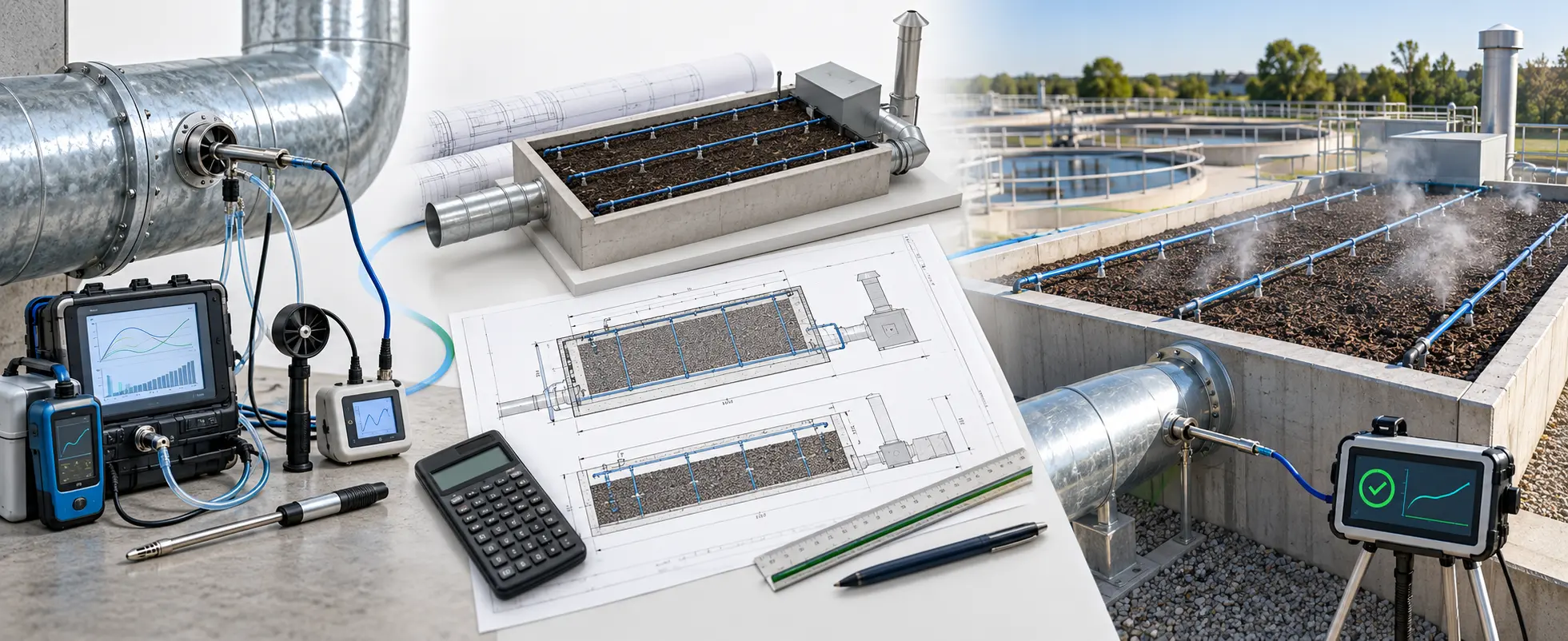
A biofilter contains 5,625 ft3 of installed media and is being evaluated for service involving mixed odors and biodegradable VOCs. At a preliminary target EBRT of 45 seconds, the corresponding airflow through the operating media bed is:
5,625 ft3 × 60 ÷ 45 seconds = 7,500 ACFM
At 30 seconds, the same media volume corresponds to 11,250 ACFM; at 60 seconds, it corresponds to 5,625 ACFM. Increasing airflow reduces EBRT unless installed media volume is increased.
4. Relationship Between EBRT, Bed Depth, and Face Velocity
For a uniform media bed, EBRT also links bed depth and superficial face velocity. This relationship provides a quick cross-check of the proposed airflow, bed area, and media depth.
| Media Depth | 15-second EBRT (fpm) | 30-second EBRT (fpm) | 45-second EBRT (fpm) | 60-second EBRT (fpm) |
|---|---|---|---|---|
| 3 ft | 12.0 | 6.0 | 4.0 | 3.0 |
| 4 ft | 16.0 | 8.0 | 5.3 | 4.0 |
| 5 ft | 20.0 | 10.0 | 6.7 | 5.0 |
| 6 ft | 24.0 | 12.0 | 8.0 | 6.0 |
Face velocity (fpm) = Media depth (ft) × 60 ÷ EBRT (seconds). This relationship does not replace pressure drop, media support, drainage, or airflow distribution calculations.
5. Why the Same EBRT Does Not Mean the Same Performance
Contaminant Characteristics
Hydrogen sulfide, reduced sulfur compounds, amines, and individual VOCs differ in solubility, biodegradability, and oxidation rate. A mixed stream may require additional volume or multiple treatment stages.
Mass loading and peaks
EBRT describes air volume, not contaminant mass. Inlet mass loading is the contaminant mass flow entering the bed divided by the installed media volume. Elimination capacity is the contaminant mass removed divided by the installed media volume. With consistent units, the corresponding expressions are Q × Cᵢₙ ÷ Vbed and Q × (Cin – Cout) ÷ Vbed, commonly reported as g/(m3•h). Peak loading may control design even when average EBRT appears adequate.
Outlet target
General odor reduction may require less treatment margin than a low numerical outlet concentration, a stringent odor limit, or a high removal efficiency guarantee.
Media and biofilm
Surface area, pore structure, moisture retention, resistance to compaction, buffering, and biological activity influence mass transfer and long-term capacity.
Airflow distribution
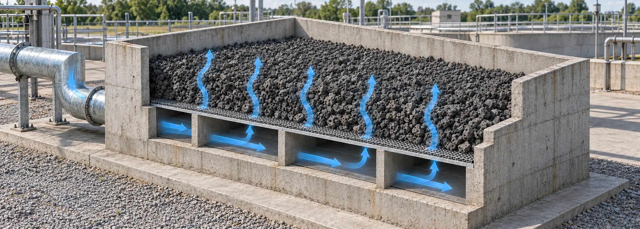
Channeling and dead zones reduce effective bed use. Uniform underdrain distribution and a level media bed installed to a consistent depth are essential.
Operating environment
Moisture, inlet relative humidity, irrigation, nutrients, temperature, pH, and acclimation affect microbial activity. A favorable EBRT cannot compensate for a dry or biologically inactive bed.
Differences Between Biofilters and Biotrickling Filters
Conventional biofilters and biotrickling filters should not be assigned the same residence time solely because both use biological treatment. Reactor type, recirculating-liquid chemistry, contaminant speciation, mass loading, and operating conditions must be considered with EBRT.
6. Recommended Design Workflow
GES Biotek design perspective
GES Biotek generally begins preliminary evaluation of many packed-bed odor and VOC biofilters in the 30- to 60-second range. Shorter EBRTs require favorable treatability, loading, and operating conditions. Mixed VOCs, reduced sulfur compounds, stringent outlet limits, or significant peaks may require additional media volume, pilot testing, pretreatment, or staged treatment.
Recommended workflow
- Define normal, maximum, minimum, future, upset, and reduced-cell airflow cases; confirm whether airflow is reported in ACFM or SCFM.
- Characterize average and peak H2S, reduced sulfur compounds, ammonia/amines, individual VOCs, odor concentration, temperature, and humidity.
- Set the required outlet concentration, removal efficiency, averaging period, and performance test conditions.
- Select a preliminary EBRT range based on contaminant treatability, loading, operating experience, and design margin.
- Calculate the required installed media volume and select a feasible combination of bed area, depth, and face velocity.
- Check inlet mass loading, elimination capacity, pressure drop, media support, drainage, irrigation, and nutrients.
- Confirm uniform airflow distribution and evaluate duty, standby, and cell-out-of-service scenarios.
- Allow adequate biological acclimation before final performance testing.
7. Design Checklist
| Design item | Confirm before finalizing EBRT |
|---|---|
| Airflow | Normal, peak, minimum, future expansion, fan turndown, cells in service, ACFM or SCFM basis |
| Contaminants | Average and peak concentrations, individual species, odor units, solubility, and biodegradability |
| Performance | Required outlet concentration, removal efficiency, averaging period, and test method |
| Media bed | Installed bulk volume, active depth, area, porosity, pressure drop, and support system |
| Biological conditions | Moisture, inlet relative humidity, temperature, pH, nutrients, seed source, and acclimation |
| Hydraulics | Irrigation coverage, drainage, ponding prevention, nozzle overlap, and recycled-water quality |
| Air distribution | Headers, laterals, underdrain, smoke testing, and uniformity acceptance criteria |
| Operations | Seasonal conditions, downtime, bypass, maintenance access, monitoring, and alarms |
Conclusion
EBRT is an essential preliminary sizing parameter because it converts installed media volume and actual airflow into a common basis for comparison. GES Biotek generally begins preliminary evaluation of many packed-bed odor and VOC biofilters within the 30- to 60-second range. Selected, well-characterized odor systems may support shorter EBRTs, while difficult or highly variable service may require additional media volume, pilot testing, pretreatment, or multiple treatment stages.
Final sizing must consider EBRT together with contaminant mass loading and treatability, media selection, face velocity, pressure drop, humidification, irrigation, nutrient availability, airflow distribution, drainage, and acclimation requirements. Final design should be based on project-specific data and governing performance requirements.
Technical References
- U.S. Environmental Protection Agency. Off-Gas Treatment Technologies for Soil Vapor Extraction Systems: State of the Practice. EPA-542-R-05-028. March 2006. Source
- Iranpour, R., Cox, H.H.J., Deshusses, M.A., and Schroeder, E.D. Literature Review of Air Pollution Control Biofilters and Biotrickling Filters for Odor and Volatile Organic Compound Removal. Environmental Progress, 24, 254-267, 2005. doi:10.1002/ep.10077. Source
- Cox, H.H.J., Deshusses, M.A., Converse, B.M., Schroeder, E.D., and Iranpour, R. Odor and VOC Treatment by Biotrickling Filters: Pilot-Scale Studies at the Hyperion Treatment Plant. Water Environment Research, 74(6), 557-563, 2002. doi:10.2175/106143002X140369. Source
- Omri, I., Aouidi, F., Bouallagui, H., Godon, J.J., and Hamdi, M. Performance Study of a Biofilter Developed to Treat H2S from Wastewater Odour. Saudi Journal of Biological Sciences, 20(2), 169-176, 2013. doi:10.1016/j.sjbs.2013.01.005. Source
Important engineering note: This paper provides general preliminary design guidance. Project-specific selection must be confirmed using current airflow, contaminant data, operating conditions, media properties, system configuration, and governing performance requirements.