A two-layer upflow bed places Cell-Max™ Plus (CMP) at the inlet to support biological hydrogen sulfide removal and Enhanced Cell-Max™ Plus (ECMP) above it to treat residual odors and biodegradable organic compounds. This arrangement assigns different media to successive treatment duties while retaining one footprint and one airflow path.1-3
We recommend considering this arrangement when H2S is a substantial part of a mixed odor stream. The lower layer must have enough volume for the incoming sulfur load, and the upper layer must have enough contact time for the remaining compounds. The layer ratio is a design decision; it should follow the contaminant profile and required outlet performance.
Recommended upflow arrangement
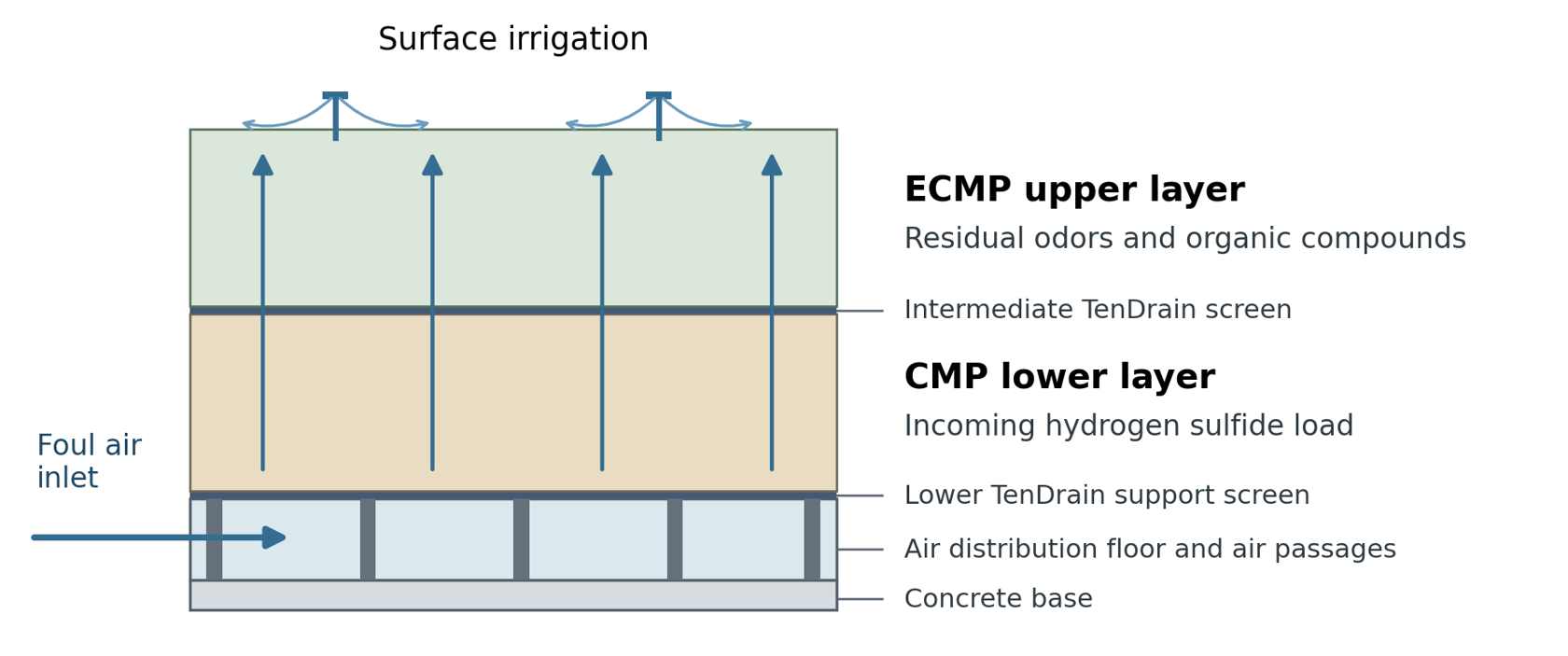
Figure 1. Air passes through CMP first and ECMP second; irrigation water drains downward. Layer depths and the support floor are project specific.
Scope: This paper explains the engineering rationale, sizing method, installation requirements, and verification approach. It applies to a contiguous two-layer biofilter; separately controlled vessels may be needed where each biological stage requires its own liquid chemistry.
Colored Rendering of the Two-Layer Bed
The cutaway below shows the media layers, support screens, air distribution floor, and irrigation in one basin. Blue arrows show foul air moving upward from the floor through the CMP and ECMP layers.
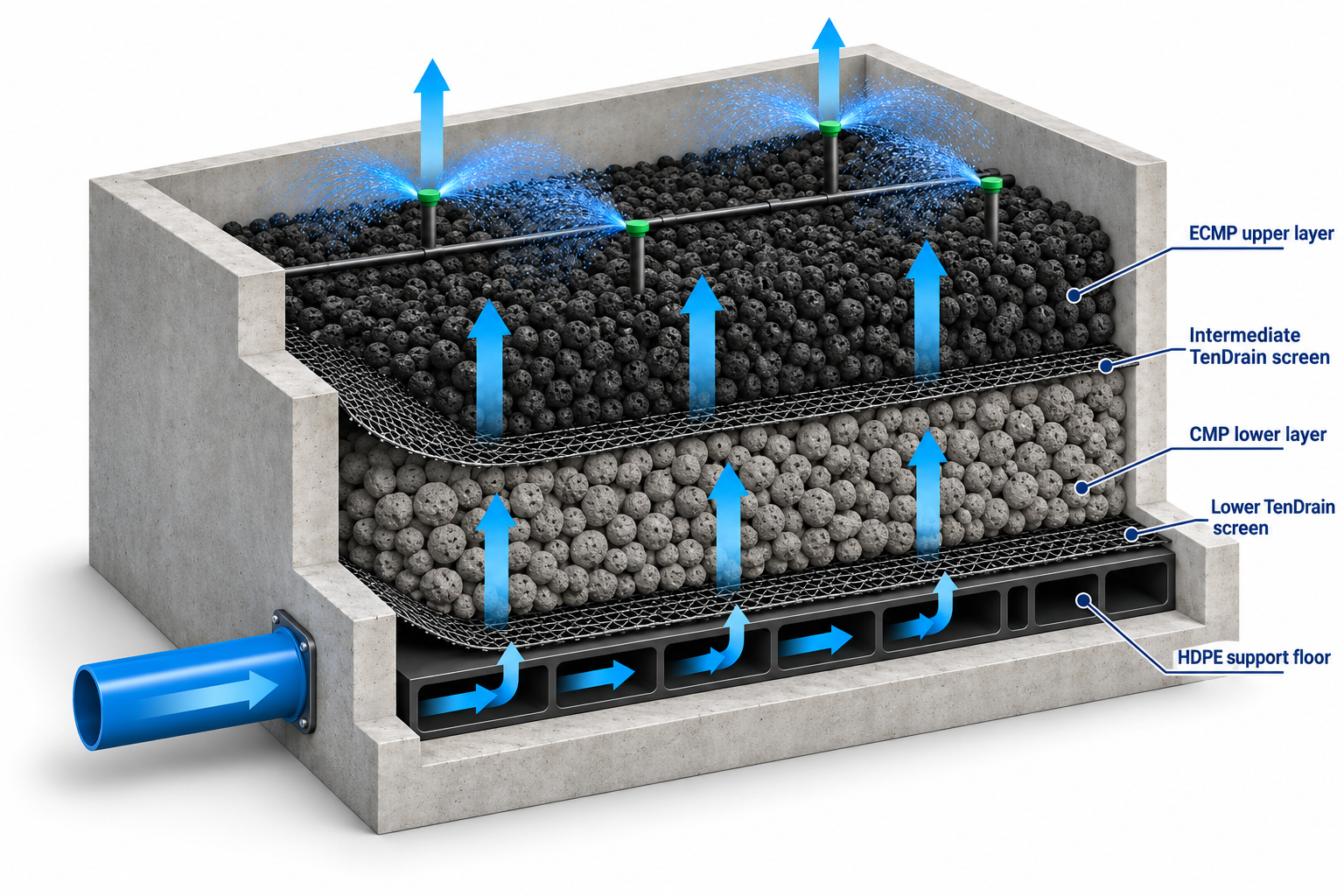
Figure 2. Labeled CMP and ECMP biofilter cutaway showing both HDPE support screens, the HDPE support floor, upflow air, and surface irrigation.
The gray lower media represents CMP, and the black upper media represents ECMP. A thin HDPE support screen sits above the distribution floor, with a second screen at the media interface. The floor contains internal air passages and rests on the concrete base.
This is a conceptual arrangement only. Media depth, particle grade, screen details, floor geometry, irrigation coverage, and drainage must follow the approved project design. The rendering is not a dimensioned construction detail.
Media Properties and Treatment Roles
CMP is an acid-resistant recycled-glass substrate suited to sulfur-oxidizing microorganisms. ECMP uses the same type of rigid substrate with a proprietary nutrient and mineral matrix, including adsorbents and organic carbon sources, to support a broader bacterial and fungal community. Both substrates resist biological decomposition, and both media can participate in H2S treatment; their roles are not exclusive.1-3
| Media property or weight basis | CMP | ECMP |
|---|---|---|
| Intended duty in this arrangement | Incoming H2S treatment | Residual odor and organic compound treatment |
| Laboratory tested dry bulk density** | 11 lb/ft3 | 11.5 lb/ft3 |
| Laboratory tested operating wet bulk density** | 13 lb/ft3 | 14.5 lb/ft3 |
| Laboratory tested fully flooded weight** | 45 lb/ft3 | 43 lb/ft3 |
| Dry weight per cubic foot** | 11 lb/ft3 | 11.5 lb/ft3 |
| Operating wet weight per cubic foot** | 13 lb/ft3 | 14.5 lb/ft3 |
| Fully flooded weight per cubic foot** | 45 lb/ft3 | 43 lb/ft3 |
| Reported water holding capacity* | 2.0 lb/ft3 | 2.4 lb/ft3 |
| Reported surface area* | 400,000 m2/m3 | 49,000,000 m2/m3 |
| Crushing load at 15 percent strain* | 13,000 lb/ft2 | 13,000 lb/ft2 |
| Media warranty subject to terms* | 20 year pro-rated | 20 year pro-rated |
* GES published material properties.
** GES laboratory-tested weights and calculated loading values. Dry means before wetting; operating wet means normal irrigated operation. Fully flooded means media plus retained water when completely submerged or flooded. This is a conservative maximum-loading condition for structural review and is not representative of normal biofilter operation.1-4
L = ρ × d
Media structural load L (lb/ft2) equals bulk density ρ (lb/ft3) multiplied by media depth d (ft). Media weights in the chart are expressed per cubic foot.
Surface area and porosity require careful interpretation
Reported surface area describes a material property. It does not establish how much area is wetted, biologically accessible, or supplied with oxygen and contaminant under operating conditions. The higher ECMP value should not be converted into a proportional removal-rate increase or a shorter required EBRT without performance data.
Internal particle porosity and open interparticle flow space describe different features. Airflow and drainage depend on the connected spaces in the installed, wetted bed. A particle pore-volume percentage is not a substitute for installed-bed void space, gas residence time, or a flooded-load test.
CMP in this paper means Cell-Max™ Plus selected for biofilter service. CMP-1 and CMP-2 are distinct particle grades and require their own approved gradation, density, airflow, and hydraulic data.
Why Sequential Treatment Can Help
Match the biological population to the contaminant
Sulfur-oxidizing autotrophic organisms can use H2S as an energy source and inorganic carbon for growth. Organisms treating many organic odorants use organic substrates for energy and carbon. Media chemistry, biofilm conditions, and the actual compounds determine which populations remain active. A dedicated CMP inlet layer allows the ECMP portion to be positioned downstream of the principal H2S treatment zone.1-2
Reduce sulfur loading before organic odor treatment
Complete biological oxidation of H2S to sulfate generates acidity. A simplified net reaction is:
H2S + 2O2 → SO42– + 2H+
The inlet region normally receives the greatest H2S mass load and can develop the most acidic conditions. Reducing H2S before the upper layer may reduce sulfur oxidation and acid generation within that upper zone. This is a design rationale, not a prediction that ECMP will remain at a particular pH.
Rene and colleagues studied a first-stage biotrickling filter followed by a fungal biofilter treating H2S, methanol, and alpha-pinene. The acidic first stage removed most of the H2S and methanol; the second stage at a higher pH removed most of the alpha-pinene. Their results support matching successive biological duties to suitable conditions. They do not establish CMP or ECMP removal rates or validate a particular layer ratio.5
Keep the limits of a shared bed clear
An intermediate HDPE support screen limits particle migration. Water, dissolved acidity, and nutrients can pass through it. Consequently, two contiguous media layers do not provide the independent pH and liquid control of two vessels with separate irrigation or recirculation systems. If the upper biological duty requires a controlled neutral environment, evaluate independent stages rather than assuming the screen provides chemical isolation.
Treat each remaining compound on its own basis
Mercaptans, other reduced sulfur compounds, amines, and individual VOCs have different transfer and biodegradation rates. Low outlet H2S does not prove low total odor. ECMP selection should follow compound-specific data and the odor target. Ammonia duties require additional review of pH, alkalinity, oxygen demand, and nitrogen fate; absorption into acidic water alone does not demonstrate sustained biological removal.
Adsorbents in the enhanced matrix may provide temporary buffering, depending on the compound and operating conditions. Sustained service depends on biological conversion; adsorption capacity must not be treated as unlimited.
Size Each Treatment Layer
Both layers receive the full design airflow in series. Use actual airflow at the bed inlet for EBRT, and keep the gas-flow and concentration reporting bases consistent. A layer receives only its share of the total contact time.6-7

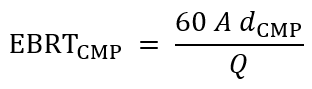
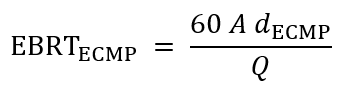
A = active bed area in ft2; d = installed layer depth in ft; Q = actual airflow in ft3/min. Results are in seconds. Superficial face velocity equals Q/A in ft/min. EBRT uses gross media volume and is not the measured residence time through open pores.
Illustrative geometry and loading
| Design Item | Illustrative Value |
|---|---|
| Active area and design airflow | 1,000 ft2 and 7,500 acfm |
| Lower CMP and upper ECMP depths | 2.5 ft each; 5.0 ft total |
| Installed layer and total volumes | 2,500 ft3 each; 5,000 ft3 total |
| Layer EBRT and total EBRT | 20 seconds each; 40 seconds total |
| Superficial face velocity | 7.5 ft/min |
| Example inlet H2S | 25 ppmv at 25°C and 1 atm |
| H2S inlet mass rate | Approximately 444 g/h or 0.98 lb/h |
| H2S inlet loading on CMP volume | Approximately 6.27 g/m3 of CMP/h |
For the example, 25 ppmv H2S corresponds to approximately 34.83 mg/m3, and the airflow is approximately 12,743 m3/h. The inlet load divided by the 70.79 m3 CMP volume gives 6.27 g/m3/h. Dividing by the entire bed would give 3.13 g/m3/h and would understate the loading assigned to the CMP treatment duty.
The illustration assumes gas flow and ppmv are on the same basis. Correct measured gas conditions and dry or wet reporting bases before applying it to a humidified system. Evaluate elimination capacity from the mass actually removed by each layer, using intermediate sampling where practical.
This example is a calculation, not a rated capacity. GES uses 30-60 seconds as a preliminary screening range for many mixed odor and VOC biofilters, with selected odor-only duties evaluated at 15-30 seconds. Confirm total and layer-specific requirements against peaks, temperature, biodegradability, and the required outlet limit.7
Air Distribution Drainage and Structural Loading
Preserve uniform contact through both layers
Provide a distribution floor or underdrain suited to the footprint and design airflow. Install the lower support screen, CMP, intermediate screen, and ECMP to the approved detail. Level each layer, maintain its specified depth, and avoid segregation, concentrated dumping, excessive fines, or repeated traffic. The media bed cannot correct a poorly balanced inlet distribution system.
The HDPE triplanar geonet provides support at the floor and limits migration at the media interface. Confirm its orientation, overlaps, perimeter treatment, and compatibility with the particle grade. It supplements the support floor; it does not replace the floor or establish its load rating.3
Check the full system pressure and drainage
Add losses through CMP, ECMP, both screens, the support floor, and the inlet and outlet components at design airflow. Check the wetted condition and provide fan margin for biomass growth, fines, and seasonal operation. Dividing a bed into layers does not inherently lower pressure loss relative to a single-media bed of the same depth.
Surface sprinklers or pop-up sprays must wet the full footprint. Add subsurface irrigation where needed to reach the lower zone. Keep drainage open and prevent ponding; trapped water reduces air-filled flow space and can raise both pressure loss and structural load. Confirm where drainage goes and how sulfur oxidation products are removed.
Separate operating weight from flooded weight
| Condition for the worked example | Load on bed area | Total media and retained water weight |
|---|---|---|
| Dry using CMP 11.0 and ECMP 11.5 lb/ft3 | 56.25 lb/ft2 | 56,250 lb |
| Operating using CMP 13.0 and ECMP 14.5 lb/ft3 | 68.75 lb/ft2 | 68,750 lb |
| Flooded using CMP 45 and ECMP 43 lb/ft3 | 220 lb/ft2 | 220,000 lb |
Layer load equals bulk density multiplied by layer depth; total area load is the sum of the two layer loads. Use the dry values for dry handling calculations and the operating values for the stated normal wet condition. Flooded review requires a separate basis that accounts for water occupying the available bulk-bed spaces.4
The structural review must also include the floor, screens, piping, access loads, and any water above the media under the governing blocked-drain condition. Verify the final flooded unit weight and load combinations for the specified media and project. The particle crushing result at 15 percent strain is not an allowable design load for the floor or vessel.
Choose the Arrangement for the Actual Duty
| Arrangement | When to Evaluate It | Main Design Question |
|---|---|---|
| CMP only | H2S dominates and organic odor treatment is limited | Can the required sulfur removal and total odor limit both be met? |
| ECMP only | Organic or mixed odors dominate, or experience supports one enhanced bed | Are full-depth enhancement and the liquid conditions justified? |
| CMP below ECMP | Substantial H2S with remaining organic odor compounds | Is each layer large enough, and is shared liquid chemistry acceptable? |
| Independently controlled stages | Treatment duties need different pH or nutrient conditions | Are separate irrigation, drainage, or recirculation systems necessary? |
Use media placement to evaluate cost
A two-layer bed can reserve ECMP for the volume needed for the downstream duty. If the ECMP unit price exceeds the CMP price, the material saving relative to an all-ECMP bed of equal total volume follows directly from the CMP volume and the price difference:
Material saving = VCMP (pECMP – pCMP)
V is installed media volume; p is the current quoted cost per unit volume. Obtain current project pricing and keep purchase allowance separate from installed volume.
Include the second screen, installation sequence, irrigation changes, freight, and labor in the comparison. Both media are lightweight; truck counts depend on bag sizes, packing, and volume limits as well as weight. Layering alone does not establish a freight or energy saving. Lifecycle value depends on demonstrated performance and the maintenance required to retain airflow and biological activity.
Operate the bed as an active biological system
Maintain near-saturated inlet air, with approximately 98 percent relative humidity or greater as the GES operating target. Keep each zone uniformly damp and freely draining. The former 40–60 percent gravimetric moisture criterion for wood-chip or hog-fuel media should not be transferred to ECMP; establish a repeatable site-specific moisture baseline if analytical testing is retained.8
Approximately 1 percent of gross bed volume per day, usually divided into two cycles, is an initial GES irrigation setting. For the example, this is about 374 gallons per day. Adjust it for coverage, loading, drainage, airflow, and season. Inert substrate and an enhanced matrix do not remove the need to verify nutrient availability.8
Trend temperature and pH at consistent locations within both layers. Allow biological acclimation, commonly about six weeks or longer under continuous suitable loading, before acceptance testing. When correcting performance, make one operating adjustment at a time and allow enough time to observe the response before changing the next setting.
Verify the Bed and Confirm the Design Basis
Document airflow distribution at three installation stages: the uncovered distribution floor, the completed CMP layer, and the full CMP-ECMP bed. Smoke observation can reveal obvious bypass or uneven discharge. Record airflow and pressure measurements as well; smoke alone does not prove contaminant removal.
After acclimation, verify inlet and outlet H2S, the required odor metric, and specified organic compounds under agreed loading and airflow conditions. Intermediate gas sampling helps determine whether the lower stage is reducing H2S as intended and how much treatment remains for ECMP. Compare pressure, moisture, pH, and temperature with the operating baseline.
Information required for final selection
Confirm normal and peak airflow; average and peak H2S; organic sulfur and VOC speciation; ammonia or amine loading where present; outlet limits and averaging periods; available area and depth; fan capacity; irrigation water chemistry and supply; drainage; seasonal conditions; and structural constraints. Establish these before fixing the layer split or promising removal efficiency.
GES recommends a CMP lower layer with an ECMP upper layer where sulfur treatment and residual organic odor treatment both require dedicated volume. The benefit comes from matching media placement and biological conditions to the treatment duty. Adequate layer-specific residence time, uniform airflow, and controllable moisture and liquid chemistry remain essential.
Technical References
- NIST. Circumference Area and Volume. Geometric area and volume formulas. Accessed October 2 2026. Source
- GES Biotek. Cell-Max Plus product literature and specification sheet v4.0, July 28 2025. Published substrate properties and H2S duty. Source
- GES Biotek. Enhanced Cell-Max Plus product page and All Products page. Enhanced matrix, published properties, and reported surface area. Accessed October 2 2026. Source
- GES Biotek. Two Layer Engineered Biofilter Media System sales sheet. September 11, 2026. Layer roles and HDPE support screen. Source
- GES Biotek. Laboratory-Tested Media Weight and Structural Loading Review. Dry, operating wet, and fully flooded bulk densities and calculated loading per foot of media. Tacoma ECMP Flooded Wet Weight Engineering Response, August 19 2026.
- Rene ER, Jin Y, Veiga MC, Kennes C. Two-stage gas-phase bioreactor for the combined removal of hydrogen sulphide, methanol and alpha-pinene. Environmental Technology 30(12), 1261-1272, 2009. DOI 10.1080/09593330903196868. Source
- US EPA. Off-Gas Treatment Technologies for Soil Vapor Extraction Systems State of the Practice. EPA-542-R-05-028, March 2006. Section 5.1, pages 5-1 to 5-3. General biofiltration principles. Source
- GES Biotek. Understanding Empty Bed Residence Time technical white paper. September 15 2026. Preliminary sizing guidance. Source
- GES Biotek. Tacoma Biofilter ECMP Media Operations and Maintenance Recommendations. September 24 2026. Moisture and irrigation guidance; adapt to each installation.
Published studies cited here support general process principles. Project performance commitments require media-specific experience or testing and an agreed design and acceptance basis. A media warranty is governed by its terms and is separate from a project removal guarantee.