Biofilter, biotrickling filter, and bioscrubber describe biological air-treatment technologies, but the names are not always used consistently. The most useful distinctions are where the active microorganisms grow and how water moves through the system.
- A biofilter retains moisture in a media bed.
- A biotrickling filter passes liquid over attached biological growth.
- A classical bioscrubber separates gas absorption from biological treatment of the liquid.1-4
Purpose and Scope
This paper defines the three processes for municipal and industrial odor control and explains the overlap between engineering terminology and equipment names. It provides a common vocabulary for engineers, suppliers, and operators. The definitions apply to foul-air treatment; similarly named wastewater processes have a different treatment duty. Figures 1 through 5 show representative arrangements.
Bio-Scrubber® is a registered GES Biotek name. In this paper, lowercase bioscrubber is used as a general process term.
Comparison of the Operating Processes
| Process | Principal Location of Biology | Typical Water Operation |
|---|---|---|
| Biofilter | Attached to moist media and accessible pore surfaces | Humidification and irrigation maintain retained moisture |
| Biotrickling Filter | Biofilm attached to wetted packing | Liquid trickles over packing and commonly recirculates |
| Classical Bioscrubber | Suspended in a separate liquid bioreactor | Absorption liquid is biologically treated and returned |
How the definitions are used in this paper
Classical bioscrubber means the absorber and separate biological-liquid reactor arrangement. The broader bioscrubber name is also applied to attached-growth equipment, including systems described as fixed-film bioscrubbers or biotrickling filters. The equipment name should therefore be accompanied by a description of the biomass location and liquid circuit.2-4
Biological Oxidation in Odor Control
Biological oxidation is the process in which microorganisms oxidize absorbed or dissolved pollutants to obtain energy for growth and maintenance. In the aerobic odor-control systems discussed here, oxygen supports this conversion. The products depend on the pollutant: biodegradable organic carbon can become carbon dioxide, water, and cellular material, while inorganic sulfide can become sulfate and acidity.1, 7
How a gas reaches the microorganisms
Odorous compounds first transfer from the air into moisture on the media, into the biofilm, or into a washing liquid. Oxygen also reaches the biological layer. The organisms then metabolize the compounds. Gas-liquid contact and biological conversion are separate parts of the treatment process; adequate contact alone does not establish that a pollutant has been biologically destroyed.1-3
Organic odors and inorganic sulfur
| Pollutant group | Biological function | Representative products |
|---|---|---|
| Biodegradable organic compounds | Heterotrophic organisms use organic carbon as a carbon and energy source | Carbon dioxide, water, and new biomass |
| Hydrogen sulfide and other reduced inorganic sulfur | Sulfur-oxidizing organisms obtain energy from sulfur oxidation; autotrophic organisms use carbon dioxide for cell carbon | Sulfate and acidity under complete aerobic oxidation; elemental sulfur may form under other conditions |
Hydrogen sulfide contains no carbon. A definition restricted to consuming organic substances in wastewater therefore does not fully describe biological odor control. The microbial community and its operating environment must match the actual contaminant mixture. 7
Meaning of biofiltration
Biofiltration is an established name for a process combining pollutant transfer with microbial conversion. The word filter describes the treatment bed and contact arrangement; odor removal includes metabolic conversion rather than only physical particle capture. Biological oxidation explains the mechanism, while biofilter, biotrickling filter, and bioscrubber describe equipment arrangements.1-4
Why organic and inorganic are separate descriptors
Organic and inorganic describe the media composition. GES Cell-Max™ Plus (CMP) and Enhanced Cell-Max™ Plus (ECMP) may be used individually or in a dual-layer biofilter bed, and may also be used in a GES Bio-Scrubber® bed. Media selection and arrangement depend on the contaminants and operating conditions. The media name alone does not define the treatment process.5, 6, 10
Biofilters
A biofilter is a biological air-treatment system in which contaminated air passes through a moisture-retaining media bed that supports attached microorganisms. Pollutants transfer from the air into the moist biological layer and are degraded by the organisms. The media provides the habitat and air passages needed for treatment.1, 5
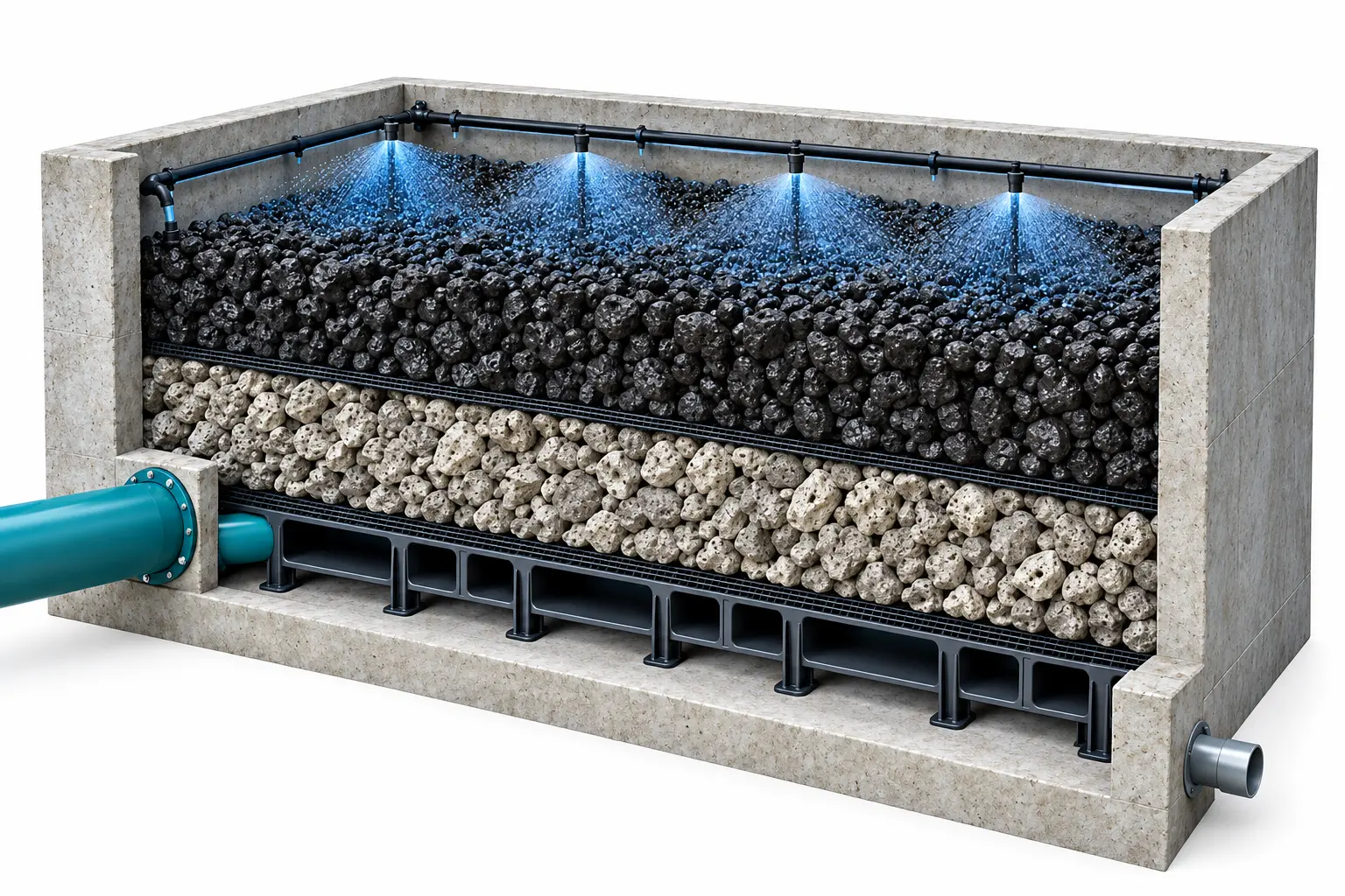
Figure 1. Conceptual GES biofilter cutaway. Gray lower media represents Cell-Max™ Plus; black upper media represents Enhanced Cell-Max™ Plus. Thin separation screens and a channelled support floor are shown. Layer proportions and irrigation hardware are illustrative.
Air path: Foul air → distribution floor → moist media bed → treated air
Liquid path: Irrigation → media wetting → collection and drainage
What makes the system a biofilter
The bed maintains a moist environment between irrigation events. Inlet humidification and irrigation replace moisture lost during operation; excess water drains away. Biofilters can be open beds or enclosed vessels. Uniform air distribution allows the contaminated air to contact the available biological surfaces.1
Traditional beds use wood, bark, or compost, which can provide part of the nutrient supply as the material ages. Engineered inorganic media provide a durable attachment structure; nutrients and moisture management are selected for the application. A biofilter may support sulfur oxidation, organic-odor degradation, or both through an appropriate media and biological arrangement.1
Biotrickling Filters
A biotrickling filter is a biological air-treatment system in which microorganisms grow as an attached biofilm on packing while a liquid phase trickles over that packing. Pollutants transfer into the liquid and biofilm and are biodegraded. The liquid commonly collects in a sump and returns to the distributor through a recirculation pump.1-2
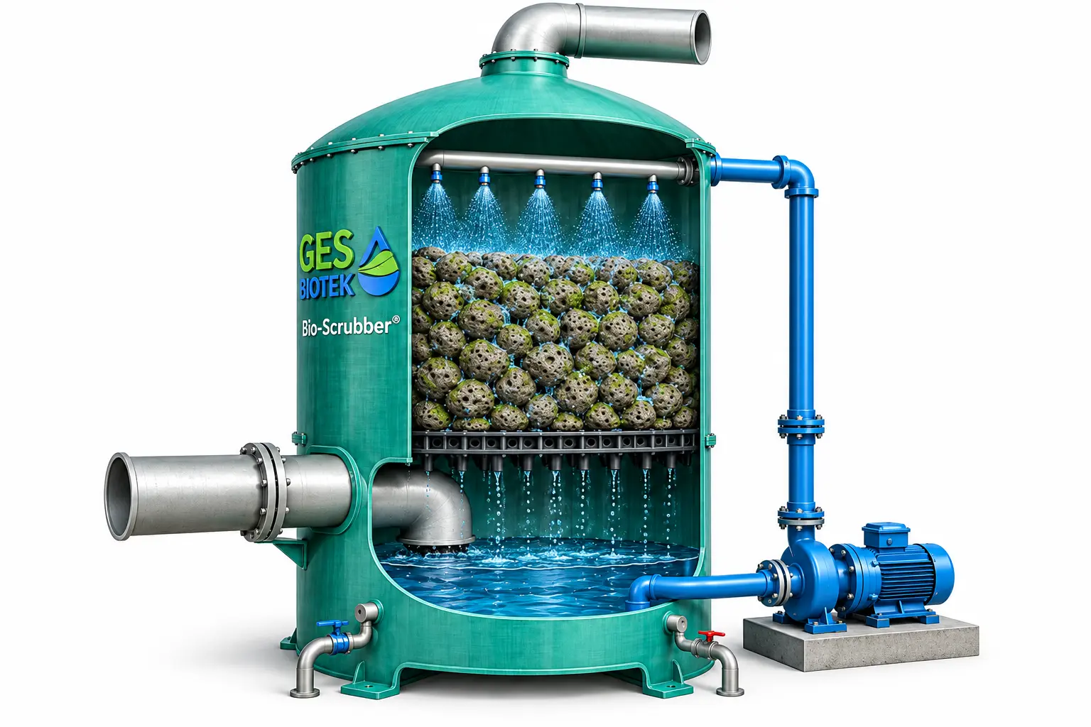
Figure 2. Conceptual GES Bio-Scrubber® operating as an attached-growth biotrickling filter. Gray CMP packing, upper sprays, a support grid, sump, and external recirculation circuit are shown. Packing and the air inlet remain above the sump liquid level.
Air path: Lower air inlet → wetted packing → upper treated-air outlet
Liquid path: Sump → recirculation pump → distributor → packing → sump
The media and liquid form a biological habitat
Acid-resistant inert packing provides attachment surfaces and passages for gas and draining liquid. The recirculating water delivers moisture, mineral nutrients, and trace elements. Treated effluent or another makeup-water source may be used when its quality suits the process. Air can move with the descending liquid or against it; Figure 2 shows opposing flows.2, 7, 8
Why it may be called a bioscrubber
Bio-Scrubber® is a registered GES Biotek name. A GES Bio-Scrubber® operated with trickling liquid over biologically active media fits the attached-growth biotrickling description. The collection sump supports recirculation; the principal biology remains on the packing. The arrangement resembles a wet packed chemical scrubber, with microbial conversion performing the biological treatment step.4-6, 8
Hydrogen Sulfide Treatment and Water Management
Sulfur-oxidizing bacteria use H2S as an energy source. Under complete aerobic oxidation, the simplified overall reaction is shown below. In the circulating water, sulfuric acid is represented by dissolved sulfate and hydrogen ions. Partial oxidation can also produce elemental sulfur.7
H2S + 2O2 → H2SO4
Acidity and blowdown
Makeup and blowdown control accumulated acidity, sulfate, and dissolved salts. The operating pH must suit the organisms and treatment duty. A range such as pH 2 to 3 can be used for a particular acidophilic H2S process; published systems also operate below pH 2. A single optimum pH does not apply to every biological system.2, 7, 8
Blowdown may return to the wastewater process after evaluation of its flow, acidity, and effect on plant treatment. Neutralization or another discharge arrangement may be needed. Acid-resistant media, vessel components, supports, piping, and pumps should be selected for the operating environment.2, 8
Treatment of a mixed odor stream
| Contaminant | Treatment description |
|---|---|
| Hydrogen sulfide | Sulfur oxidation can provide high removal when airflow, loading, liquid distribution, and biological conditions are within the design duty. |
| Organic sulfur compounds and VOCs | Removal depends on the compounds, microbial community, pH, and contact time; further biological or carbon treatment may be required. |
| Ammonia and amines | Acidic liquid can absorb and retain basic compounds. This capture is distinct from biological nitrification and transfers material to the liquid circuit. |
Performance and equipment capacity
An H2S removal result alone does not establish total-odor removal. Define average and peak inlet loading, the outlet target, actual airflow, and testing conditions. GES reports greater than 99% H2S removal in its Stockton case study, which describes two 27,500 cfm towers. These are installation-specific examples; neither a 10,000 cfm vessel limit nor a universal inlet-concentration range defines the process.8, 9
A biological first stage can reduce the H2S load on a downstream biofilter or carbon bed. Biological treatment can also reduce bulk chemical-oxidant demand compared with chemical scrubbing, while water, nutrients, pumping, fan energy, and maintenance remain operating requirements.7, 8
Classical Suspended Growth Bioscrubbers
A classical suspended-growth bioscrubber is a biological air-treatment system that combines a gas absorber with a separate liquid bioreactor. The absorber transfers pollutants into a washing liquid. The liquid then enters the bioreactor, where suspended microorganisms degrade the absorbed compounds before the liquid returns to the absorber.3, 4
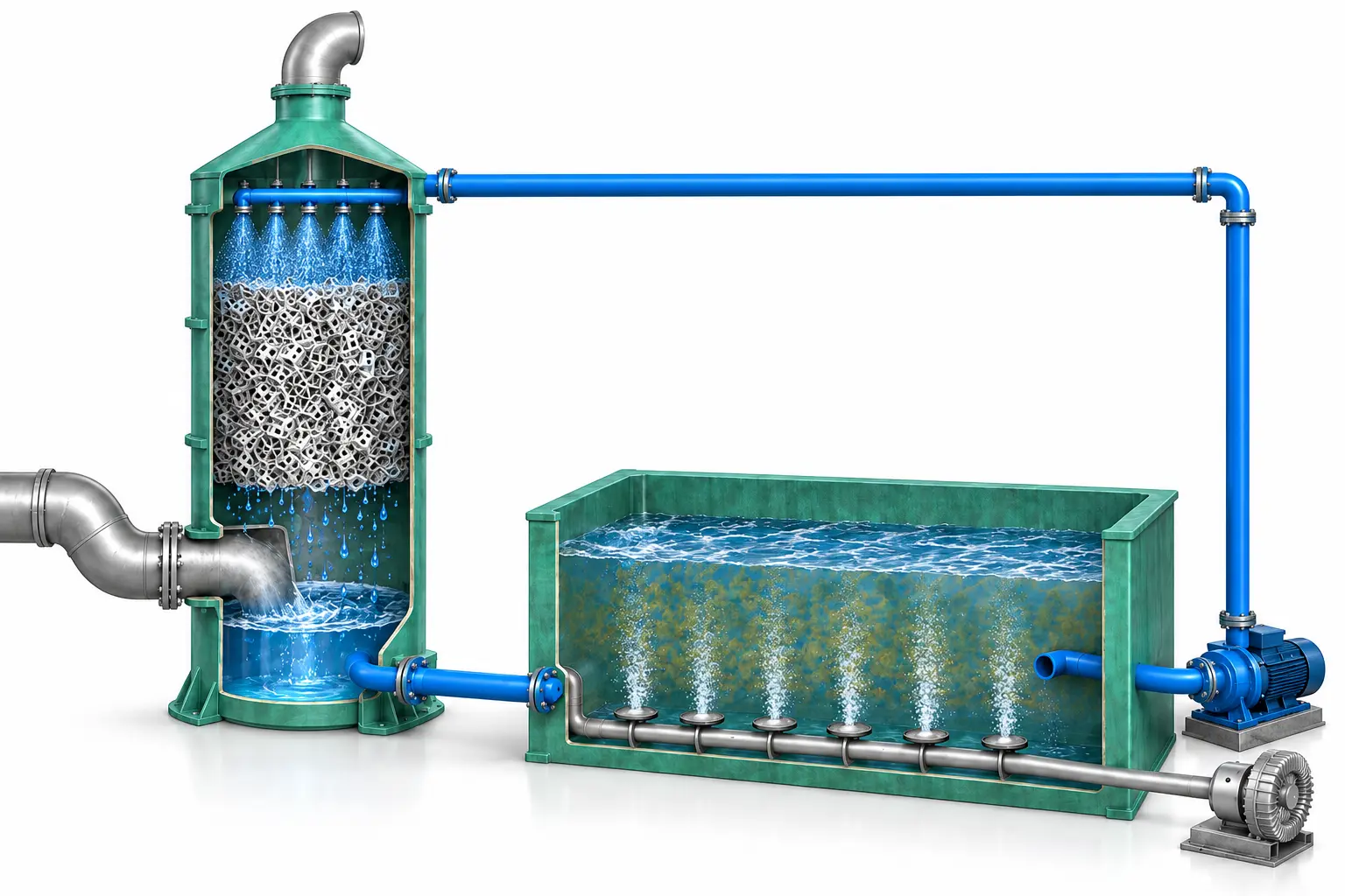
Figure 3. Conceptual classical bioscrubber. The gas absorber is on the left and the separate aerated biological tank is on the right. Absorber packing promotes gas-liquid contact; the main biomass is suspended in the tank. Connections are illustrative.
Air path: Foul air → gas absorber → treated-air outlet
Liquid path: Absorber collection → biological tank → pump → absorber distributor
Where the biological reaction occurs
In the arrangement illustrated, the biological tank provides liquid residence time, aeration, and mixing for suspended biomass. Absorber packing provides gas-liquid contact. The absorber and biological reactor can be designed for their separate duties of pollutant capture and liquid regeneration.3, 4
A separate liquid reactor can also use attached growth or a hybrid biological arrangement. The phrase suspended-growth bioscrubber identifies the particular biomass arrangement shown here. A separate tank is classified by its treatment function; a recirculation reservoir by itself does not establish this process.3
GES Two Stage System Above Ground
In this conceptual arrangement, the first stage is a GES Bio-Scrubber® for bulk H2S treatment. Its air outlet feeds the lower air-distribution space of a second-stage biofilter. The second stage provides further treatment of the remaining odor mixture using an application-specific biological ecosystem. The rendering shows both treatment units above grade.
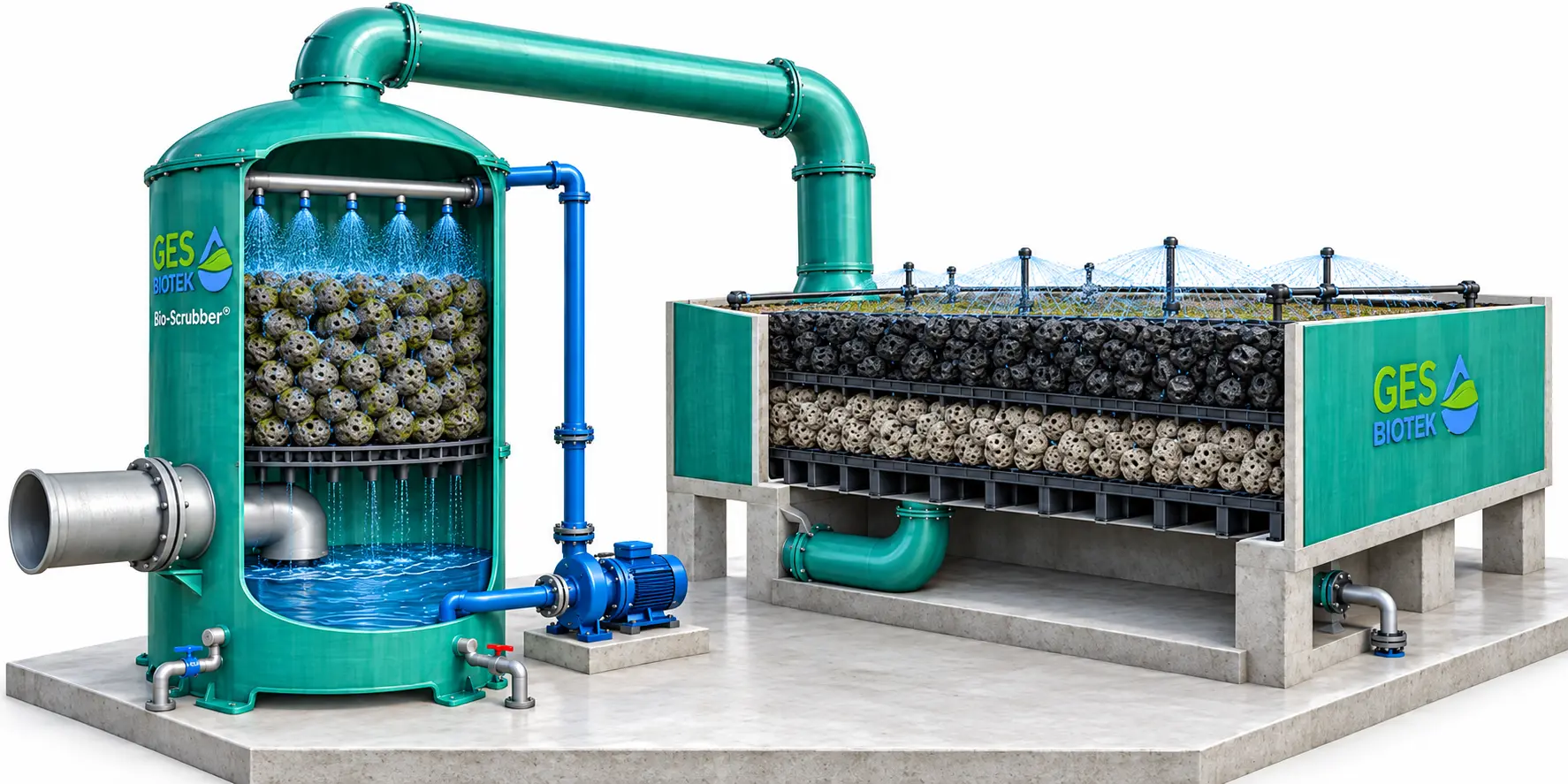
Figure 4. Conceptual above-ground GES two-stage system. Stage 1 is a Bio-Scrubber®; stage 2 is a biofilter with gray CMP below black ECMP. The gas duct connects the tower outlet to the biofilter distribution floor. Liquid circuits and drainage are separate.
Treatment sequence: Foul air → Bio-Scrubber® → dual-layer biofilter → treated air
Media layers and treatment stages
CMP and ECMP may be used as individual media beds or combined in a dual-layer bed. Where selected, gray CMP forms the lower layer and black ECMP the upper layer, with the support and separation screens shown conceptually. Both media may also be used in a Bio-Scrubber® bed when selected for that operating duty.6, 10
Two media layers within one biofilter are a dual-layer bed. Two separate treatment units connected in series are a two-stage system. Layer depths, stage duties, irrigation, and recirculation must be established for the actual airflow and contaminant loading.
GES Two Stage System Above Ground
The treatment sequence can remain the same when the second-stage biofilter is recessed below grade. In this rendering, the GES Bio-Scrubber® and its recirculation pump remain above ground, while the biofilter media, support floor, and distribution space lie below grade. The biofilter top is open at approximately finished grade.
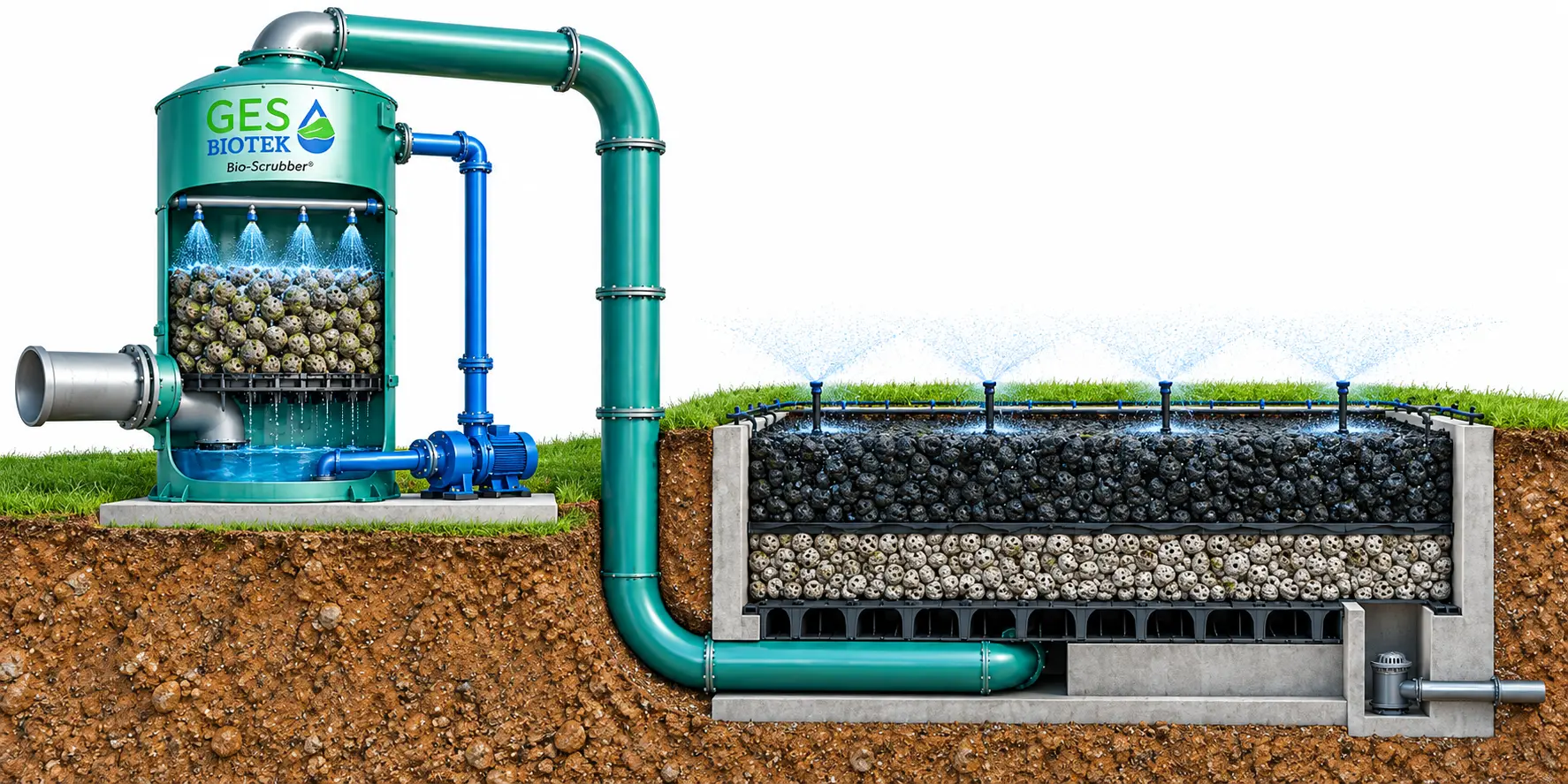
Figure 5. Conceptual GES two-stage system with a below-ground biofilter. A soil cutaway exposes the gray CMP lower layer, black ECMP upper layer, support floor, and inlet duct. The Bio-Scrubber® remains above grade. Dimensions and equipment proportions are illustrative.
Air path: Tower outlet → below-grade gas duct → distribution floor → CMP and ECMP layers
Installation elevation and process naming
Above-ground and below-ground describe the installation elevation. The second stage remains a biofilter because it uses attached biological growth in a moisture-retaining media bed. The first stage remains an attached-growth Bio-Scrubber® because of its biological packing and trickling-liquid operation.
A below-ground arrangement requires a project-specific drainage, groundwater, structural, and access design. Neither the elevation nor the number of media layers changes the underlying treatment-process definition.
Why the Names Become Confused
The same bioscrubber label can describe different biological arrangements. Engineering literature distinguishes suspended-growth bioscrubbers from fixed-film bioscrubbers, while biotrickling filter describes attached growth contacted by trickling liquid. These overlapping names explain why two suppliers can use different terms for similar equipment, or the same term for different equipment.2-4
| Name or description | What it tells the reader | What needs clarification |
|---|---|---|
| Biofilter | Biological treatment in a moist media bed | Media type and moisture-management arrangement |
| Biotrickling filter | Attached biofilm contacted by trickling liquid | Liquid circuit and recirculation operation |
| Bioscrubber or biological scrubber | Biological treatment associated with gas washing | Attached or suspended growth and biological-reactor location |
| Fixed-film bioscrubber | Biomass attached to packing | Whether the unit operates as a biotrickling filter |
| GES Bio-Scrubber® | A registered GES Biotek name | The actual packing, biomass location, and liquid operation |
Media and water operation need separate descriptions
Organic and inorganic identify media composition. Biofilter and biotrickling filter identify how the biological treatment process operates. An inorganic media bed can be an irrigated biofilter, and inorganic packing can also support a biotrickling process.5, 6
Spray nozzles, a drain, or a recirculation pump are individual components. Classify the complete operating arrangement: moisture retained between irrigation events, trickling liquid over attached biomass, or biological regeneration in a separate liquid reactor. Irrigation schedules can overlap, so nozzle timing alone is an incomplete definition.
Spelling and related terms
Biotrickling filter is also written bio-trickling filter or bio trickling filter. These spelling variations normally refer to the same process. A wastewater trickling filter treats pollutants carried in wastewater; the foul-air biotrickling filter described here treats pollutants arriving in a gas stream.1
Using Clear Names in Project Documents
We recommend pairing the process name with one sentence stating where the biomass grows and how the liquid operates. The following descriptions can be used when they match the actual equipment arrangement.
| Process name | Example description |
|---|---|
| Engineered inorganic biofilter | Foul air passes through a moisture-retaining inorganic media bed supporting attached microorganisms; humidification and irrigation maintain bed moisture. |
| Attached-growth biotrickling filter | Foul air contacts biologically active packing while liquid trickles through the bed and returns through a recirculation circuit. |
| Suspended-growth bioscrubber | A gas absorber transfers pollutants into liquid that is biologically treated in a separate aerated tank before returning to the absorber. |
When a commercial bioscrubber name is used, add the applicable process description. This gives the engineer and operator a consistent explanation of the equipment even when the supplier terminology differs.
References
- U.S. EPA. Using Bioreactors to Control Air Pollution. EPA-456/R-03-003, September 2003. Biofilter and biotrickling process descriptions. Source
- VITO EMIS. Biotrickling Filter. LUSS technical sheet. Attached biofilm and circulating liquid operation. Source
- VITO EMIS. Bioscrubber. LUSS technical sheet. Gas absorber and separate biological reactor; biological-reactor variants. Source
- Ockeloen HF, Overcamp TJ, and Grady CPL Jr. Engineering Model for Fixed-Film Bioscrubbers. Journal of Environmental Engineering 122(3), 191-197, 1996. Abstract distinguishes attached and suspended growth. Source
- GES Biotek. Understanding Biofilter Media Selection. Current online technical guidance.Source
- GES Biotek. Cell-Max™ Plus. Current online product description.Source
- Gabriel D and Deshusses MA. Retrofitting Existing Chemical Scrubbers to Biotrickling Filters for H2S Emission Control. PNAS 100(11), 6308-6312, 2003. Sulfur oxidation and full-scale treatment.Source
- Gabriel D, Cox HHJ, and Deshusses MA. Conversion of Full-Scale Wet Scrubbers to Biotrickling Filters for H2S Control at Publicly Owned Treatment Works. Journal of Environmental Engineering 130(10), 1110-1117, 2004.Source
- GES Biotek. Bio-Scrubber® Tower System Stockton CA. Case study reporting tower capacity and H2S removal.Source
- GES Biotek. Enhanced Cell-Max™ Plus. Product description and media application guidance.Source
Online references accessed October 4, 2026. Renderings illustrate representative configurations and do not establish dimensions or performance.